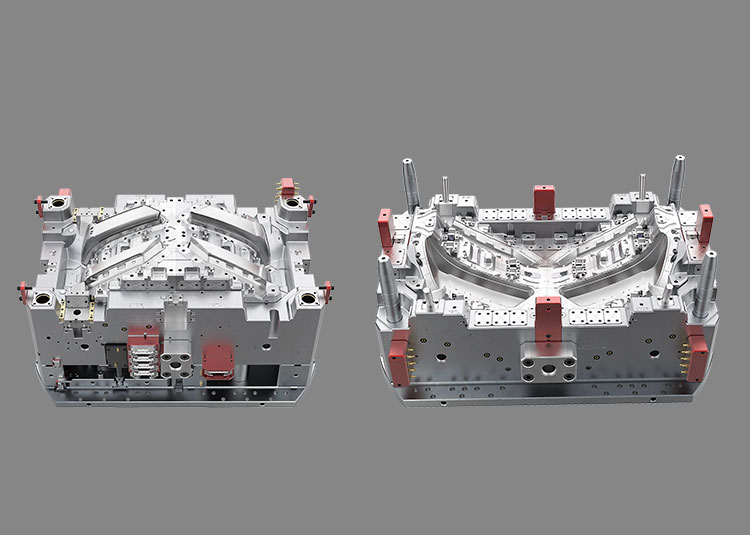
Before approving a weld-line prediction, agree where converging melt fronts may meet, which product requirements apply there and what trial evidence will close the decision. A simulation plot helps organise this review; it is not a strength certificate or proof that a surface will show no line. This guide covers weld and meld lines within an injection-moulded part, rather than adhesion between different materials in a two-shot part.
1. Mark the regions that matter
On the current drawing, identify visible surfaces, load-bearing features and any regions with an optical or sealing function. Ask the responsible product engineer to mark locations where a weld line is prohibited, conditionally acceptable or still undecided. A hidden surface may still carry a functional requirement.
For each region, name the requirement, inspection or test method and approval owner. Keep appearance and function as separate decisions. A line that is difficult to see is not automatically acceptable under load; a visible line is not automatically a failed part when its location and criteria have been agreed.
2. Make the simulation assumptions traceable
If a filling analysis is supplied, request its model revision, exact material data, gate and runner arrangement, and proposed processing assumptions. Identify provisional inputs. Autodesk's Moldflow guidance asks users to represent the moulded geometry, thickness changes, material and process accurately, and to inspect the filling sequence alongside the weld-line output.
For a Moldflow study, ask the analyst to explain mesh quality and the result being displayed. Keep the original study or agreed report reference, not only a cropped screenshot. A study for a different resin grade or gate layout does not silently approve the current proposal. Confirm who supplies and reviews the analysis; this checklist does not imply that Jump Mould owns a particular simulation package.
3. Read the flow history, not just a coloured line
Ask the analyst to show how the melt fronts split and meet, and which temperature and meeting-angle information the reported result represents. Autodesk explains that mesh density affects weld-line prediction and describes reviewing temperature with the result. These are interpretation inputs, not universal acceptance limits.
An empty weld-line plot cannot prove that the moulded part will have no weld lines. Autodesk separately documents cases where actual weld or meld lines are missing from a simulation. Ask which model and solver limitations could affect the region being reviewed, and retain unresolved uncertainty in the trial plan. Do not infer a strength value from the plot colour.
4. Compare a proposed change against the whole part
When a gate, runner, geometry or process assumption changes, request an updated study reference and compare the same critical regions. Record the proposed benefit, affected requirements and what still needs a trial. Moving a predicted line away from one visible area does not approve filling, dimensions or performance elsewhere.
Use the actual material supplier's guidance for material-dependent questions. Avoid copying a temperature, meeting-angle threshold or solver setting from a general example into a different project. The approved product requirements and the responsible engineering review determine the acceptance route.
5. Connect trial samples to separate acceptance decisions
For reviewed samples, retain the cavity, drawing revision, resin grade and available batch and trial-condition records. Mark observed line locations on the same region map used for the prediction review. If an observed location differs, reopen the relevant assumption or requirement instead of treating the simulation as the final result.
Record visual inspection under agreed conditions separately from any required mechanical, sealing or optical evaluation. Identify who provides samples, fixtures and test results. Unknown performance stays open; a photograph cannot close a functional test.
A review entry you can copy
Use one entry per critical region: region ID; drawing revision; requirement and status; analysis reference and assumptions; predicted location; trial sample and cavity; observed location; visual result; required functional result; owner; next action and closure evidence.
For example, a region beside an assembly feature can remain conditional until both the agreed appearance check and the required functional evaluation are recorded. This is an example of a review record, not a tested design or customer case.
Bring the review into your tooling enquiry
Prepare the current CAD and drawings, material status, region map, any supplied analysis and the open acceptance questions. Jump Mould's catalogue shows tooling and part examples; feasibility and analysis scope still need to be agreed for your project. The cover shows two catalogue mould assemblies, not a weld-line prediction or trial result.
Headlamp tooling and parts: https://www.jumpmould.com/products/catalogue-headlight-1
For the wider DFM review, read our design checklist: https://www.jumpmould.com/journal/ten-mould-design-tips
Discuss project inputs at https://www.jumpmould.com/contact or email sales@jumpmould.com.
Technical references
The following Autodesk documents concern Moldflow interpretation. Reviewed 7 October 2026; their numerical examples are not project acceptance specifications.
How to better predict weld and meld lines in Simulation Moldflow Insight: https://www.autodesk.com/support/technical/article/caas/sfdcarticles/sfdcarticles/How-to-better-predict-weld-and-meld-lines-in-Simulation-Moldflow-Insight.html
Utilizing and understanding weld line results in Moldflow: https://www.autodesk.com/support/technical/article/caas/sfdcarticles/sfdcarticles/Utilizing-and-Understanding-Weld-Line-Results.html
Molded part weld line does not show in Moldflow: https://www.autodesk.com/support/technical/article/caas/sfdcarticles/sfdcarticles/Molded-part-weld-line-does-not-show-in-simulation-in-Moldflow.html
Discuss your project