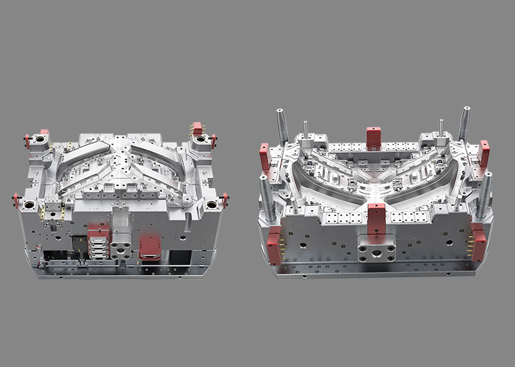
A plastic insert can sit correctly in an open mould and still move or deform when the second material is injected. Before a TPE insert-overmoulding trial, agree how the substrate will be located, supported and sealed, and what evidence will confirm each condition. The checklist below is a suggested project review record, not a universal tooling specification.
1. Name the process route and the substrate
Overmoulding describes moulding one material over a substrate. Insert moulding is one way to do it: an existing substrate is loaded into the mould. A multi-shot route can form and transfer the first shot within the moulding sequence. These descriptions overlap; they are not competing material categories. Avient lists insert, multi-shot and rotary or shuttle arrangements for its GLS TPEs.
Record the proposed route, substrate drawing revision, exact resin grade and additives, cavity identity and loading method. For separately moulded inserts, also record the first-shot batch and condition at loading. Material compatibility needs its own review; a correctly seated insert does not prove adhesion.
2. Separate locating surfaces from support surfaces
On a section view, identify the features that set the insert's position and the surfaces that support it during filling. Mark exposed ribs, hollow areas and thin sections for review. Avient's design guide explains that an unsupported plastic insert can deform under TPE injection pressure; insert displacement can also produce flash. That is a design-review reason, not a prediction that every insert will fail.
Ask the tooling team to show the intended load path and explain which areas remain unsupported. Record whether support would mark a visible surface, interfere with a functional feature or complicate removal. Where the incoming substrate dimensions vary, agree how that variation will be assessed rather than checking only one nominal CAD model.
3. Define the shut-off boundary
The shut-off is the mould-to-substrate contact boundary intended to keep the second material out of selected areas. It must be reviewed together with the substrate shape and the venting arrangement. Avient's part-design guidance discusses shut-offs for a defined TPE boundary and control of flash.
Mark the overmoulded zone, the keep-clear zone and the transition line on the same drawing revision. Identify contact faces, any visible contact marks that need acceptance, and the dimensions affecting closure. Ask how shrinkage, sink or dimensional variation in the first shot could change contact. Agree project-specific closure and vent details with the tooling and material teams; do not copy a supplier's example interference or vent dimensions into an unrelated material and part.
4. Record seating before evaluating the finished part
Agree how the team will confirm insert orientation, full seating and cavity identity before the trial, using the approved equipment procedure. A locating photograph or annotated section can make the intended position easier to discuss. It does not replace a validated loading check.
For each reviewed trial sample, retain the substrate batch, cavity, loading method and applicable drawing revision alongside the recorded process conditions. If the substrate is transferred while warm, record the relevant transfer condition. Avient's processing guidance notes that a first shot needs enough strength to resist the second shot without remelting or distortion; the appropriate condition depends on the actual grade and process.
5. Keep three acceptance questions separate
Position: did the substrate and the overmoulded zone remain within the agreed dimensional requirements?
Boundary: did the transition and keep-clear areas meet the agreed appearance and flash criteria?
Bond: did the material interface pass the specified adhesion or functional test?
Assign a sample ID and evidence to each result. When a defect appears, compare the insert condition, location, support and shut-off evidence before concluding that the resin is the cause. Avient's troubleshooting guide lists mould fit, shut-off design and substrate shrinkage among possible flash causes, and inadequate support among possible causes of damage to a hollow substrate.
A review record you can copy
Create one row for each locating feature, support area and shut-off segment. Use these fields: feature ID; drawing revision; intended contact or support; incoming substrate condition and dimensional range; trial sample and cavity; acceptance requirement; observation or measurement; responsible reviewer; open action and closure evidence.
For example, a visible transition can have separate entries for permitted flash, permitted contact marks and the measurement method. Keep an unknown requirement open with an owner. Do not mark it approved because a photograph looks acceptable, and do not treat an adhesion result as dimensional approval.
Bring the evidence into the tooling discussion
Prepare the substrate and finished-part CAD, controlled drawings, material grades, proposed route, loading information and acceptance requirements for a tooling review. Jump Mould's two-shot tooling catalogue provides examples for multi-material tooling discussions; project feasibility and the proposed insert-loading arrangement still need review against the actual part.
Cover image: a mould photograph from Jump Mould's catalogue. It is not an insert-location diagram or evidence of a completed trial.
For material-interface questions, also read our TPE overmoulding adhesion checklist: https://www.jumpmould.com/journal/tpe-overmolding-adhesion-checklist
For a project discussion, use https://www.jumpmould.com/contact or email sales@jumpmould.com with the current drawing revision and the open review items.
Technical references
The following Avient documents concern its GLS TPE overmoulding guidance. Their examples and numerical settings are not universal specifications. Checked 5 October 2026.
Overmolding Design Guide, “Mold Layout and Support” (PDF page 12): https://www.avient.com/sites/default/files/2020-10/tpe-overmold-design-guide.pdf
Overmolding: Part Design, “Shut-Off Design”: https://www.avient.com/resources/knowledge-base/article/overmolding-part-design
Overmolding: Processing, “Machine Selection” and “Substrate Temperature”: https://www.avient.com/resources/knowledge-base/article/overmolding-processing
Overmolding: Troubleshooting, flash and hollow-substrate observations: https://www.avient.com/resources/knowledge-base/article/overmolding-troubleshooting
Discuss your project