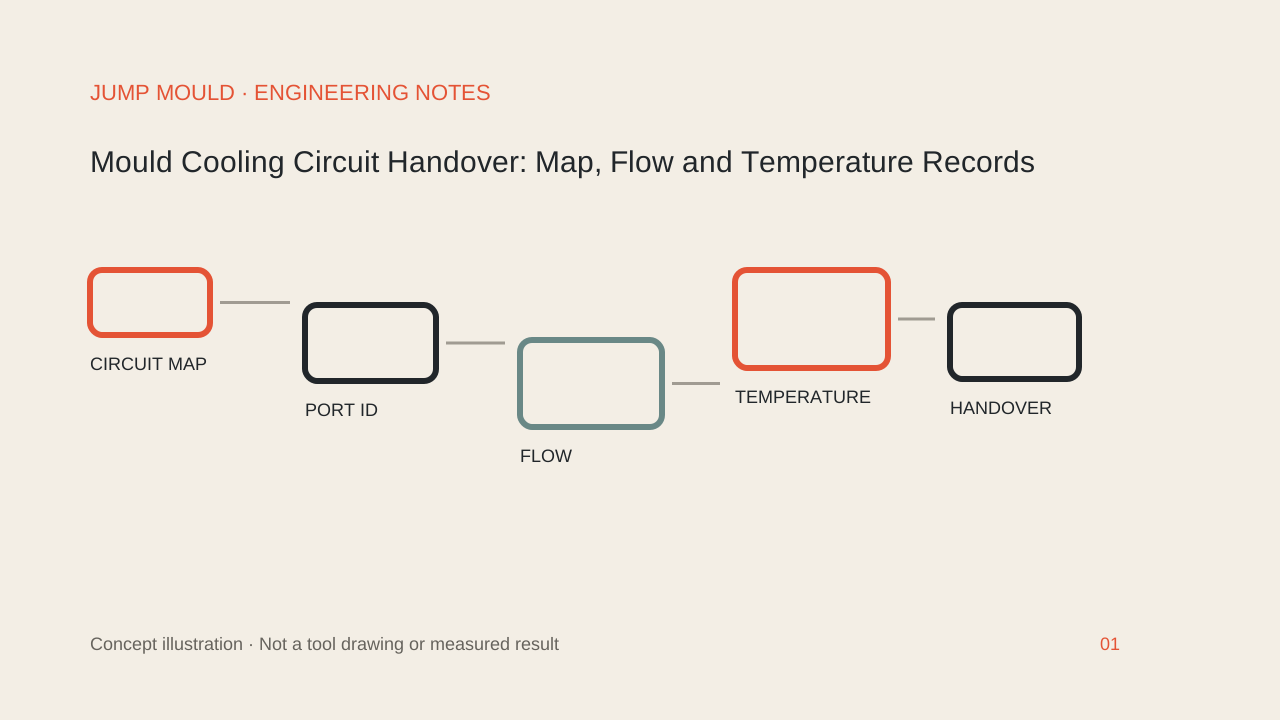
A mould cooling handover should connect each physical circuit to a current drawing, the available coolant supply and a measured trial record. Agree what will be recorded at the supplier and what must be checked again at the receiving plant. A controller setpoint or a single pressure reading does not complete this record.
This is a suggested handover checklist for product engineers and tooling buyers. It does not prescribe channel dimensions, test pressures, coolant settings or a guaranteed cycle time.
1. Make a circuit map that survives a hose change
Give each circuit a stable identifier and mark its inlet, outlet, connected mould section and intended flow direction on the current drawing. Show the proposed series or parallel arrangement and any external manifold. Match drawing labels to the physical ports and the connection list.
Record the connector specification, hose arrangement and which party supplies each item. Ask who confirms compatibility with the intended temperature-control unit and plant services. Leave undecided interfaces open; a photograph of the mould does not establish the internal circuit route.
For moving mould sections, include connection access and the required movement review. This checklist does not replace the machine–mould interface approval.
2. Record the available supply and each circuit's condition
Autodesk's cooling-circuit guidance distinguishes pressure-based, flow-rate-based and Reynolds-number-based simulation inputs. It also explains that a total flow can divide unevenly among parallel branches. Ask which input represents the intended plant supply and which values have actually been measured.
On the handover sheet, keep the unit, measurement location and circuit ID beside every value. Where pressure drop is evaluated, identify the inlet and outlet measurements and their locations; a supply-pressure figure alone leaves that comparison incomplete. Do not treat the manifold total as a measurement of every branch.
If a cooling analysis is supplied, retain the model revision, coolant properties, boundary conditions and report reference. Ask the analyst to identify provisional inputs. A simulated result remains separate from a measured trial record, and this guide does not imply that Jump Mould operates any particular analysis software.
3. Distinguish settings from temperatures at different locations
Keep the controller setpoint, measured coolant inlet temperature, measured outlet temperature and any mould-surface measurements in separate fields. Record where and how each temperature was taken and which trial condition it belongs to.
Autodesk's cooling tutorial displays circuit-coolant temperature and mould–circuit interface temperature as different results. Its example values are not acceptance limits for your mould. Likewise, DME describes monitoring pressure, temperature and flow in cooling circuits; those are distinct measurements, not interchangeable evidence.
For a proposed acceptance range, identify who sets it and the relevant product, material and process requirements. Leave an unagreed limit open rather than borrowing a tutorial number or claiming that one temperature setting works for every tool.
4. Keep a trial baseline with its setup
Before dispatch, agree a baseline record for the configuration used in the trial. Include the mould revision, circuit map, coolant identity, connected equipment, hose and manifold arrangement, instruments and measurement time. Record whether the values came from circulation alone or from an actual moulding trial, and identify the corresponding process and sample records where available.
Agree any required leak or continuity check separately, including its method, authorised conditions, result and responsible person. Do not insert a generic pressure or duration into the handover specification. A missing measurement is an open item, not a zero or an assumed pass.
Review part dimensions, appearance and other required functions through the project's own sample-acceptance process. Cooling measurements help describe the setup; they do not by themselves approve the part or establish a production cycle-time promise.
5. Make receiving-plant checks comparable
Ask the receiving team to confirm circuit labels and connections against the delivered drawing. Repeat the agreed measurements with the new setup identified. If equipment, coolant, hoses or operating conditions differ, record that difference before comparing the two sets of numbers.
For a changed circuit or an unexpected result, assign an owner and an agreed investigation or retest. Keep the original baseline and the new record together. The useful outcome is a traceable decision about the difference, rather than silently replacing an earlier value.
A handover entry you can copy
Use one entry per circuit:
- Circuit ID and drawing revision; inlet, outlet, mould section and connection arrangement.
- Coolant and supply equipment; intended conditions, actual setup and unresolved interfaces.
- Measured flow, inlet and outlet pressures, inlet and outlet temperatures, units and measurement locations; unavailable items marked open.
- Instrument reference, measurement time, circulation-only or moulding-trial context, and related sample record.
- Required check method and result; agreed limits and approval owner; receiving-plant comparison and next action.
For example, a circuit can have complete connection labels while its receiving-plant flow check is still open. That is a record status example, not a tested Jump Mould project or a prescribed acceptance value.
Bring the handover scope into your tooling enquiry
Send the current product files, proposed circuit map, available plant-service information and handover questions to Jump Mould. Our catalogue provides tooling and part examples; the actual design, measurement responsibilities and acceptance scope need to be agreed for your project. The cover is a catalogue mould photograph, not a cooling diagram, instrument reading or trial result.
Headlamp tooling and parts: https://www.jumpmould.com/products/catalogue-headlight-1
For the wider review, read the mould design checklist: https://www.jumpmould.com/journal/ten-mould-design-tips
Discuss project inputs at https://www.jumpmould.com/contact or email sales@jumpmould.com.
Discuss your project