A two-shot mould can be designed for the right product yet still need changes to run on the intended machine. Once the product regions and material requirements are defined, the tooling team and moulding team need a separate interface review. Its output is a dated, approved record of the proposed mould and the actual machine configuration.
1. Identify the actual machine and transfer arrangement
Record the machine model, its installed options, the current manufacturer drawings and the proposed mould revision. A model name or clamping-force figure alone is an incomplete description of the installation.
Name the proposed transfer method and draw the sequence between shots. ARBURG describes core-back, transfer and turning mould technologies; ENGEL also distinguishes different multi-component process arrangements. These are alternatives to evaluate, not interchangeable labels for one universal two-shot machine.
On the sequence drawing, show which component or mould assembly moves, what holds the first-shot part and when the finished part is removed. Ask the machine supplier and mould designer to confirm which arrangement the actual installation supports. Keep a proposed configuration separate from an installed, verified option.
2. Review the full movement envelope
Overlay the proposed mould assembly and its movement on the machine manufacturer's current installation drawing. Include the mould dimensions, mounting details, available opening travel and the space required by the selected transfer arrangement. Where applicable, include tie-bar clearance, ejector movement and handling access.
Check the positions used during opening, transfer and removal, not just the closed mould outline. Identify hoses, cables and connectors that need access or move with an assembly. ARBURG's ALLROUNDER MORE description specifically discusses space for moulds, rotary units, media connections and ejector travel; the actual limits must come from the intended machine's documents.
Record each unresolved clearance as an open item with a drawing reference and an owner. Do not copy a dimension from a different machine or treat a catalogue photograph as a fit check.
3. Map each injection unit to its mould interface
For each shot, identify the injection unit, its position and the intended injection point. Request confirmation of the nozzle connection details and approach position against the actual mould design. Have the responsible machine and process teams review the proposed material and shot requirements against that unit's available specification.
List any assumptions about a second unit, adapter or auxiliary equipment explicitly. An unconfirmed upgrade should stay conditional in the quotation. A successful trial on another machine does not close this review unless the relevant interfaces have been compared and accepted.
4. Assign utilities, signals and sequence responsibilities
Make a connection list for the proposed configuration: cooling, electrical connections and any required hydraulic or pneumatic services. Identify which side supplies each connection, what information is still needed and who approves the arrangement. Use the applicable supplier specifications; this checklist supplies no standard pressure or connector value.
For any controlled transfer or handling equipment, ask the integrator to document the sequence, required position confirmations and machine interfaces. Agree who verifies the completed installation under the manufacturer's procedures. The review sheet is a project handoff document, not instructions for altering control logic or bypassing machine safeguards.
5. Close the review with evidence, not an assumption
Use one row per interface: item identifier, machine document revision, mould drawing revision, requirement, evidence, owner and status. Useful statuses are confirmed, conditional and open. If an interface changes, identify the affected rows for review rather than marking the entire old sheet approved again.
Agree what the trial record must demonstrate for the accepted machine–mould configuration and which open items prevent installation or trial approval. Keep interface verification distinct from part dimensions, appearance and material-bond testing. Fitting the machine does not establish product performance.
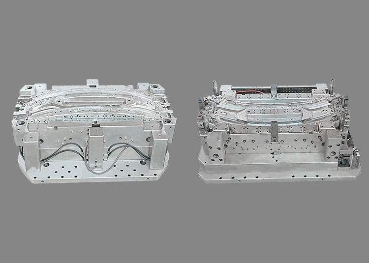
Our existing 2K versus 3K selection article discusses product functions and material choices. This checklist adds the later machine–mould handoff. Jump Mould's two-shot and 2K/3K tail-lamp catalogue pages show tooling and part photographs; they do not establish machine compatibility or trial results. The cover is a catalogue tooling photograph.
To discuss tooling scope, send the current product files, proposed process sequence, available machine drawings and open interface questions to sales@jumpmould.com. Use the website contact page to agree the project review and the information that can be shared.
Technical references
ARBURG, Multi-component injection moulding: https://www.arburg.com/en/solutions/by-technology/multi-component-injection-moulding/
ARBURG, ALLROUNDER MORE: https://www.arburg.com/en/product-world/injection-moulding-machines/electric-machines/allrounder-more/
ENGEL, Plastic surface finishing, multi-component process overview: https://www.engelglobal.com/en/products/injection-moulding-processes/plastic-surface-finishing
These manufacturer references explain available technology. They are not evidence of equipment installed at Jump Mould or approval of a particular project.
Discuss your project