Two quotations for an automotive lighting mould are difficult to compare when one supplier assumes a decorative transparent part and another assumes a tightly controlled optical component. A useful RFQ makes those assumptions visible. Start with the part's function and acceptance evidence, then discuss the tooling arrangement.
1. Mark what each surface must do
Provide a controlled 3D model, its revision and a 2D drawing for dimensions that need explicit tolerances. Mark light-entry and light-exit surfaces, appearance surfaces, assembly datums and areas where gate or ejector marks may be acceptable. A clear photograph is useful context, but it does not define an optical acceptance limit.
For a light guide, include the intended relationship to the light source and mating parts. Ask the responsible optical designer to identify the geometry that must be preserved and the agreed inspection method. For a lens cover, specify which surfaces need polishing, coating or other downstream treatment, and which party owns that work. Treat unresolved requirements as open items in the quotation rather than assumptions everyone silently accepts.
2. Specify grades and boundaries, not just colours
List the exact resin grade, supplier and colour specification for each region. If a grade has not been selected, identify the candidate and who will approve it. Optical requirements need to be checked against the chosen grade and intended use; a generic material name is insufficient. Covestro's automotive-lighting overview discusses application-specific optical properties and specialised polycarbonate grades, which is useful background rather than a specification for your part.
For 2K or 3K tooling, show the injection sequence and boundaries between regions. Different colours can use the same resin family; do not assume that every colour requires a different polymer. Ask whether each interface needs adhesion, mechanical retention, sealing or only a controlled appearance boundary. Agree how boundary flash, colour mixing and interface position will be assessed. Material compatibility requires supplier information and trials using the actual grades.
3. Discuss the tool and machine together
Share the available machine's mould envelope, platen and tie-bar limits, mounting interfaces and injection-unit arrangement. For multi-shot parts, also provide the relevant indexing or transfer arrangement and utility interfaces. Identify whether the supplier is quoting a mould for an existing machine or evaluating a process that still needs equipment selection.
During DFM, review gate locations, parting lines, venting, ejection and cooling alongside the marked surfaces. Record which decisions depend on material data, simulation or a trial. A proposal should explain its assumptions; a generic promise of high gloss or a short cycle is not acceptance evidence.
4. Agree what the first trial must deliver
Separate tooling acceptance from the final lamp assembly's optical performance and any applicable product qualification. State who owns each evaluation, what samples or fixtures are needed and which method or approved reference will be used. Do not expect an unlit loose component photograph to prove how a completed lamp will perform.
Request identifiable samples with material grade, cavity, drawing revision and trial conditions recorded. The review should cover agreed dimensions, appearance, assembly fit and any multi-shot boundary requirements. Where relevant, arrange evaluation in the actual lighting assembly under defined conditions. Log unresolved issues, the planned correction and what evidence will close each item.
5. Make the quotation assumptions comparable
Ask each supplier to list cavities, supplied tooling scope, trial scope, inspection deliverables, spare parts and exclusions. Clarify who supplies trial resin and mating components, whether coating or external optical evaluation is included, and what happens when a drawing or material changes. Compare quotations against the same approved inputs.
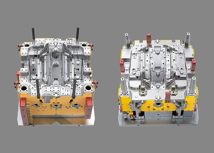
Jump Mould's catalogue includes headlamp tooling and parts, light guides and thick-wall parts, and 2K/3K tail-lamp tooling. These images show catalogue examples; they do not establish the material grade or measured results of your project. Send your drawing revision, surface map, material information, machine constraints and acceptance checklist to sales@jumpmould.com so we can discuss the tooling scope. The project contact entry below is available for your enquiry.
Reference
Covestro, Automotive lighting: https://solutions.covestro.com/en/highlights/articles/theme/applications/automotive-lighting
This checklist organises a tooling discussion. Acceptance limits come from the approved product requirements, material information and agreed tests.
Discuss your project