An automotive light guide can look clear on a desk yet still need a different assessment in the lamp assembly. Before tooling starts, agree which surfaces carry an optical function, which are visible in use and where manufacturing marks may be considered. The useful output is a controlled surface-review sheet, rather than a promise that every surface will be flawless.
1. Give each surface a function and an owner
Ask the responsible optical designer to identify the light-entry region, light-exit regions, features intended to redirect light and assembly datums on the current CAD revision. Separately mark surfaces seen by the customer. A surface can have more than one role; do not assume a hidden area has no optical function.
For each region, record its identifier, purpose, approved geometry, surface requirement, inspection method and the person who can accept a deviation. Leave undecided entries open. This makes a disagreement about a gate location or polishing requirement visible before it becomes a tooling assumption.
2. Review gate, ejector and parting-line proposals together
Have the mould designer mark proposed gate locations, ejector contact areas and parting lines on the same surface map. Review access, support and demoulding alongside the intended optical and appearance functions. This is a design review: neither a polished rendering nor a catalogue photograph establishes an acceptable mark for your component.
Specify whether a proposed location is prohibited, provisionally acceptable for a trial, or accepted under a defined condition. If trimming is planned, identify the allowed remaining vestige, its inspection method and responsibility for the operation. Set limits from the approved drawing and product evaluation; this guide supplies no universal mark size or surface-finish value.
3. Separate visual inspection from functional optical evaluation
For visual inspection, agree viewing conditions, orientation and the reference or defect catalogue to use. For functional assessment, identify the light source, mating components, assembly location and evaluation method defined by the optical team. A photograph of an unlit loose part cannot replace that assessment.
Record who performs each check and whether an external evaluation is required. If a location passes the visual check but its optical effect is unknown, retain that uncertainty as an open item. Tooling acceptance and final lamp qualification can have different owners and deliverables; make those responsibilities explicit.
4. Keep material and sample identity with the result
Use the approved resin grade and colour specification, not just a generic label such as transparent plastic. Covestro's automotive-lighting material overview describes application-specific optical requirements and grades. ENGEL's transparent-part processing guidance discusses material handling and plasticising arrangements. These are technical background, not proof of a material choice, installed equipment or performance at Jump Mould.
For trial samples, retain the drawing revision, material grade and batch information where available, cavity identifier and relevant trial conditions. Link inspection photographs and optical evaluations to those sample identifiers. If a material, geometry or process changes, agree which evidence must be repeated before accepting the revised sample.
5. Close a decision with evidence
A practical review-sheet entry might identify a proposed gate region, its current approval status, the sample to inspect, the agreed evaluation and the person responsible for the decision. Mark it closed only when the required evidence and decision are recorded. This is a documentation example, not a tested design or customer case.
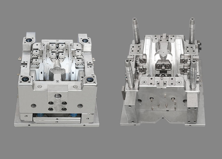
Send the current model, surface map, material status and review sheet to sales@jumpmould.com to discuss tooling scope with Jump Mould. Our light-guide and thick-wall catalogue contains tooling photographs; the cover image is a catalogue example, not an optical test result. The general automotive-lighting RFQ checklist on this website covers the wider quotation inputs. This article adds a surface-decision record for a specific tooling review.
Technical references
Covestro, Automotive lighting: https://solutions.covestro.com/en/highlights/articles/theme/applications/automotive-lighting
ENGEL, Injection moulding of transparent plastic parts: https://www.engelglobal.com/en/us/products/injection-molding-processes/transparent-plastic-parts
Apply the approved project requirements and material guidance. This checklist does not establish optical performance, regulatory qualification or a guaranteed tooling result.
Discuss your project